The hierarchy is a hierarchy on top of the graph, this means, a tree (or wood) whose leaves represent the graph nodes: For every graph node u there is exactly one hierarchy node v which is a leaf (has no children). We say, v represents u.
This allows us to group nodes of the graph who have something in common (for example common properties) or who are in any other way related by adding a common ancestor to the corresponding hierarchy leaves.
The view is a graph which is a cross section through the hierarchy. Each view node u represents a hierarchy node v (in the aforementioned meaning). Every hierarchy node can be represented by at most one view node.
Let us extend the meaning of representation to be able to relate base graph nodes and view nodes: We say, a view node u represents a base graph node w if there exists a pair of hierarchy nodes v1 and v2 where v1 is an ancestor of v2 and v1 is represented by u and v2 represents w. This means that, when relating view nodes and base graph nodes, a view node can represent more than one base graph node (in constrast to the relation between base graph nodes and hierarchy nodes, and hierarchy nodes and view nodes, where each node is represented by exactly one other node).
There are three important properties for the view:
These properties mean:
Using the view, we can represent certain currently not important parts of the base graph as just a few nodes, whereas we can get into the details of interesting parts of the base graph. This is especially useful in big graphs where it is impossible to visualize all nodes due to display limitations or the mere number of nodes (and edges).
The view can then be visualized (which was not part of this project) to display the nodes and edges for a user.
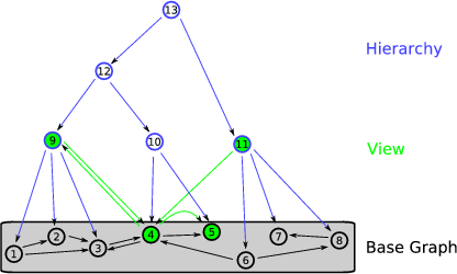
The following image shows a sample graph, with a hierarchy on top of it and a view, to demonstrate the principles.
In this image, the identifiers (IDs) of the nodes are numbers, and there are no properties of the nodes and edges.
Nodes 1 - 8 represent the base graph, Nodes 9 - 13 are the hierarchy on the graph. Node 9 for example is a parent (ancestor) of Nodes 1, 2 and 3. The top node, 13, is the root of the graph.
Our view here consists of nodes 9, 4, 5 and 11. The edges of the view represent connections in the base graph. For example, there is an edge 11->4 because of the edge 6->4. Note that no ancestor or descendant of a node in the hierarchy which is currently in the view can be in the view, too (example: nodes 1 and 9 could never be in the view at the same time).
To be able to alter the view, the hierarchy (which might cause necessary adjustments to the view) and the base graph (which might cause necessary adjustments to both the hierarchy and the view), and store IDs and properties, an interface was specified and an implementation was done. The specific requirements are discussed in the next section, details of interface and/or implementation decisions are discussed in the documentation of the respective classes and/or member functions.
To make the programming effort and the maintenance easier, a common graph library was used as a base. The Boost Graph Library (BGL), which is available as an open source project, was chosen to serve this purpose. Nevertheless, it was an important task to keep the specification generic, so that another implementation could also be written with another base graph library (such as the commercial LEDA graph library).
The main parts of the project were the graph (with properties for it's edges and nodes), a hierarchy on the graph and a view on the hierarchy. Additionally, there is the PropertyFacility and the Subject/Observer system. These parts had to be designed and implemented. It was important that these parts are as independent of each other as possible, so that it's easy to replace the implementation of a part with a new version and keep the other parts.
Another important part of the project was to implement a unit test using the specified graph/hierarchy/view/property interface to test the implementation, which can also be used to test new implementations replacing certain parts of the project.
The class Graph, which is directly derived from ConstGraph, implements the IEditableGraph interface and therefore has public methods to add and delete nodes and edges, which just use the private methods of it's parent.
To keep the implementation of the properties of the graph's nodes and edges independant from the implementation of the graph and being able to substitute either the graph or the properties implementation independently, the decision was made to move the property management into an autonomous PropertyFacility class. This is used by all graph classes derived of ConstGraph.
All nodes and edges have a graph-wide unique identifier, it's ID, which is a string. The properties in the PropertyFacility are stored for these IDs and can be of any type. (Example: The node "node1" can have a property "weight", which could be a double with the value 1.10)
In the current implementation, each graph can use it's own PropertyFacility, or more than one graph can use the same PropertyFacility at the same time. The advantage of this is easy to see: Imagine a basic graph with a hierarachy and three views. Each hierarchy node has the property "color". When all views use the same PropertyFacility as the hierarchy, the color is then consistent among all views. Even when the color is altered in one view, it will change in the others automatically.
The Hierarchy and View are both derived from the ConstGraph class. This is done because the user should not alter the graph structure of the Hierarchy and View directly. Instead, they provide specific methods, like expand(), to alter their graph structure. This ensures that they stay consistent within their requirements (the Hierarchy need to be a tree/wood, for example).
A subject/observer system exists, which can be used to send messages from any subject to it's observers. The ObservableGraph (as well as the Hierarchy and View) is derived from the Subject class, inheriting it's methods. Thus, any class derived from the Observer can add itself as an observer of the ObservableGraph and will get messages indicating changes to the graph such as creation and removement of nodes and edges and changes of IDs. Hierarchy is derived from both Subject and Observer, it observes the ObservableGraph, reacting to changes in the graph, and can be observed itself. The View is also derived from Subject and Observer, it observes the Hierarchy and the ObservableGraph, reacting to changes in both the hierarchy and the base graph.
The hierarchy keeps a reference to the underlying graph (which must be an ObservableGraph so that the hierarchy can track changes to the graph and react properly), and the view a reference to the underlying hierarchy. More than one hierarchy on a graph, and more than one view of a hierarchy can exist - they will all subscribe as observers for their graph or hierarchy and can react to changes appropriately. A hierarchy is only directly linked to it's base graph, and a view to it's hierarchy. The graphs know nothing of their hierarchies, and the hierarchies know nothing about their views, the only connection in this direction exists through the subject/observer system.
The View is intended to be observed by a visualization module, which can draw it to the screen. This was not part of this project, though.
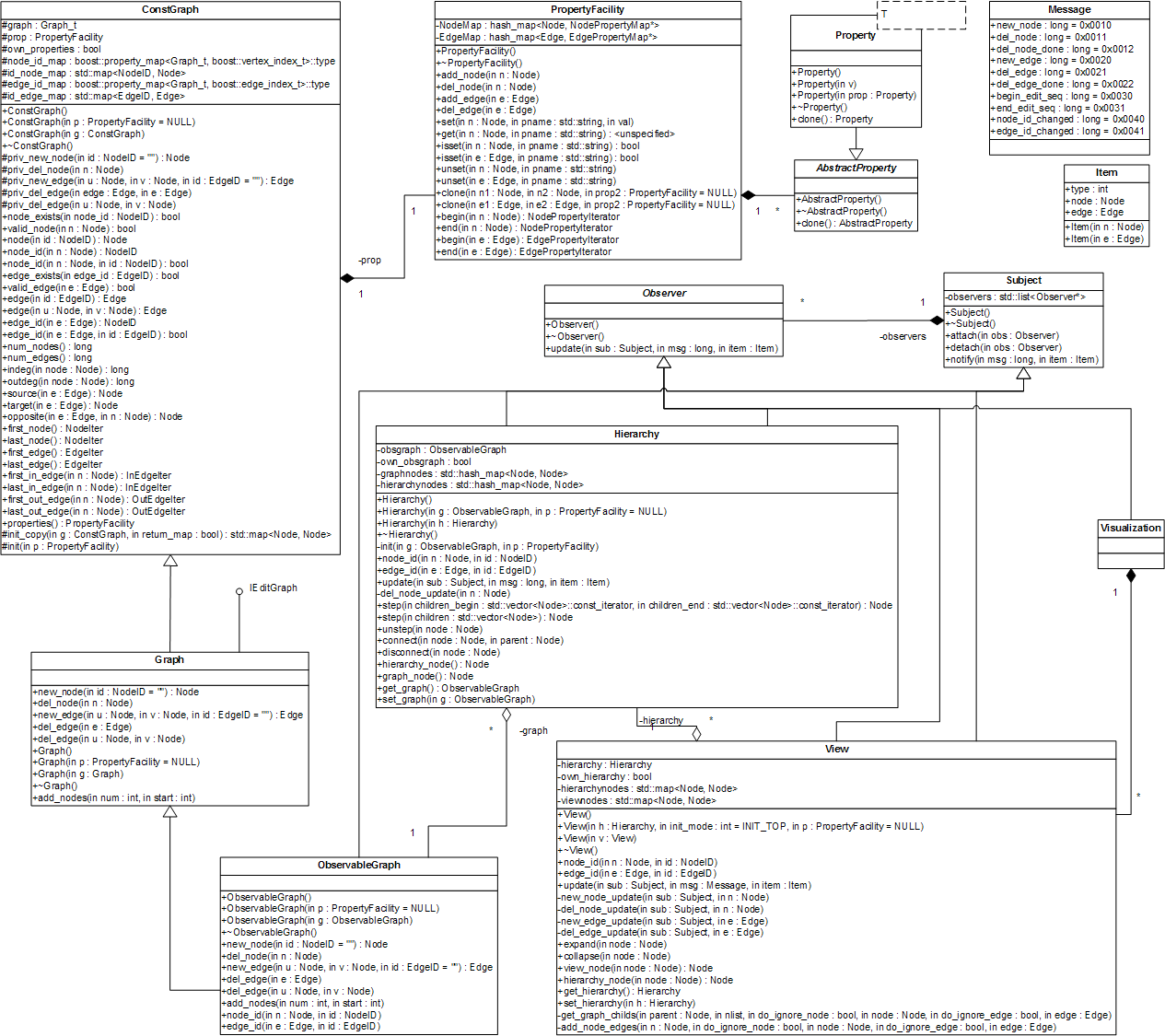
More detailed information on the classes can be found in their specific documentation. An UML diagram of the whole project is depicted in the following image.
 1.4.1
1.4.1